Tuesday, February 20, 2024

'64 Lightning Rocket - Engine Rebuild PT IV - Primary

 The clutch was a bit knackered but still probably functional as it was found. The primary chain was stretched out as the "Wardmaster socket" under the adjusting pad would indicate. This has been a common occurrence found on old bikes when I tear them apart, although two out of three had lug nuts under them. Chains must have been expensive, hard to find. or not considered worth replacing "back in the day".

Tired but still serving its purpose.

"Wardmaster socket" taking up the slack. 

New bearings & rubbers ready to bring together.

My secret weapon for putting in cush rubbers, 
It makes a seemingly impossible job very possible. 

New bearings, friction plates, greased and ready to go. 

Sprockets fit without the chain to check alignment. All is good....

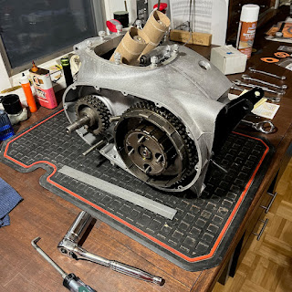
Primary parts ready for final installation & a timing disc setup being worked out. The final assembly will be done in the frame. On to the transmission & timing side.....

Timing/'TDC setup sorted. 
This will be revisited when the wiring is finished and the electronic ignition needs to be set. 

Assembly of the primary side was pretty straightforward. The rotor and stator went on passing the dollar bill test with no adjustments needed. The stator wires were fished through the case via the zip tie I had installed earlier. I am glad I did not forget that step as it is a real time saver 

Although I have never done this before I lightly oiled the clutch plates with type F automatic transmission fluid. I have always assembled them dry and they are usually oil soaked when removed. An expert in the field recommended lightly oiling them so I will give it a try. One thing that gave me fits was installing the clutch springs. Try as I might I could not get the retainer nuts to catch. After working a short while I decided to check the new springs I purchased to the originals. To my surprise they are .50 inches longer. The Lightning Rocket is specked for these longer springs although the standard Rocket springs came out of my clutch. I ordered a set of standard springs which are .25 inches longer than the originals but could not get them in either. Back to the original springs. The situation will be addressed at a later time if necessary.  Maybe a special tool?  Longer retainer screws?
Primary assembled and it's on to the timing side. 

Monday, February 12, 2024

'64 BSA Lightning Rocket - Engine Rebuild PT III - Bottom end Assembly

BSA used a ball bearing main on the drive side of their crankshaft from 62-65 with a plain bearing on the timing side. I have set the crankshaft end clearance on the later roller bearing cranks which is critical but had not assembled the ball bearing crank. The ball should hold the crank in location and there are no oil pressure concerns as on the roller bearing cranks which use a thrust washer on the timing side. The factory workshop manual shows the end clearance being set from .001 to .003 for the ball bearing crank which is the same as the roller bearing ones. The only reason I could see for this is to keep side load off of the ball bearing. If the factory says do it, do it I will. 

Crankshaft and cases were dry assembled with no shims to check end clearance. After measurement the necessary shims were added to get the .001-.003 spec. (shooting for .001 with .002 max) One note on crankshaft shim cups - Modern Hofmann ball bearings have a larger center than the originals. This requires the use of a shim cup & shims from a later roller bearing motor.

The rods were rebuilt with new wrist pin bushings and the big ends were machined to remove their oval shape. New shells, bolts and nuts finished off the rebuild. The crankshaft was assembled and checked for free movement once the rod bolts were torqued down. The case internals were installed making sure to get the camshaft and its breather assembly properly inserted.  Time to stick it together....

The bottom end and its parts ready to go. One pointer is to add the high gear and final drive sprocket before assembling the motor in the frame. Not really necessary but much easier in this order. Just trying to reduce the amount of swearing it takes to put one of these together......

Moving parts balanced......machining marks tell the tale. 

The crankshaft was shimmed and all parts were installed. Yamabond 4 was applied to the cases and they were bolted together. One final endplay check was performed after assembly and all was good. 

         
The bottom end ready to go into the frame. 

The crankcase was assembled with minimal components to keep the assembly light. This eases installation into the frame. The top end, timing side bits and the primary will be added with the engine in the frame. I took this approach on my Interceptor build with good results. I did not take this approach with my Hornet and struggled greatly with the weight of the unit. Lesson learned and on we go.......  

Frame prepped and anxiously awaiting the power egg....

Protection for the frame's new paint was added, all mounting bolts were ready to go in, and it was ready to receive the lump. The rear engine mount plates were loosely attached to aid installation. Working from the drive side the motor was installed with its front mount above the attachment point and the rear mount plates below theirs. One person was on each side of the bike to work the motor in place. The protection on the frame proved to be very necessary. 

Once the motor was in and all bolts were in the frame the lower mounts were checked for shimming. It is important to add washers to take up space between the motor and frame and not to pull the frame to the motor. (These shims are shown in the spares manual.) Bad vibrations will occur if this is not done properly. I also scrubbed the paint off of one lower mount so the engine will ground to the frame. Probably not necessary buy my electrical engineer friend says it is wise to do so I do.....

The motor is in and being built up. Adding the power egg without its heavy components worked well for two old dudes and will be my go to method. It was installed with the front mount high working it down and the rear mount a bit low working it up. This is opposite of what I have read but it worked very well.


Wednesday, July 26, 2023

'64 BSA Lightning Rocket - Carburetor Rebuild

I was pleasantly surprised that the Lightning Rocket still sported its original Monoblocs and they were in decent shape. The slide stop screws had been tightened a bit to much which put a crimp in the slides causing them to bind. Once the slides were out examination of the bodies showed they were in serviceable condition although new slides are required. Some of the fittings were rusted or had pliers put on them at some point in their life which grooved them up. One of the jet holder covers was seriously grooved. Why??!!!???!!

A bit crusty but mostly there....the original 389 Monoblocs

The slides were slightly galled and binding.

Plier marks are normal violations on these old carbs but why the grooves????

I have had good results with my ultrasonic cleaner. This takes the bits back to their core metal in most cases. I use Simple Green in the washer to assist in cleaning and have found high heat to aid in the process. I have soda blasted carbs in the past with good results but prefer the ultrasonic cleaner now that I have the process sorted.
My secret weapon...the Harbor Freight Ultrasonic

One supplement to my process this go around was to use CLR, which is a calcium and lime removing chemical, on parts with corrosion not removed by the ultrasonic. It is aggressive and should only be applied for a couple of minutes. This final step made my carb bodies look great. I finished them with a paste wax to keep the corrosion from coming back. This is my first attempt at this process and I will have to see how it plays out over time. The initial results are very good.

Parts cleaned up....ultrasonic...CLR.....wax...good to go....

Ready for assembly.....

The bores showed minimal wear so I decided to place new slides in them which worked well on my RE build. One of the foremost experts in the field says the bodies will last for 3 sets of slides if treated properly. While I have had carb bodies bored in the past I prefer not to have the expense if necessary and I do miss the choke which you sacrifice upon a re-bore. I have heard great things about the new Amal Premiers and will try them when replacements are necessary.

The bores required a slight cleanup to get the new slides to fit. High spots were sanded with 220 grit and a brake hone was used to get a tight slip fit. The mounting flange was also dressed flat with a file to correct a past mechanics over zealous wrenching. 

I chose to use the anodized slides for this rebuild. 
They are a pit pricy but I think the additional cost will be worth it. 
Ready to go, just need to set the float height.....shim if necessary. 

Time to sort out fuel taps, lines and air cleaners.......

Monday, February 27, 2023

'64 BSA Lightning Rocket - Engine Rebuild PT II - Reconditioning

Well here I am again after an absence of a year or so. In hindsight I had a great plan.  Send the engine out for machining while assembling all of the reconditioned chassis parts. Get the engine bits back, assemble, and install it in the frame for an early spring start up - April 2022.... I was not planning on the engine machining to take a year and a half to complete, parts to be difficult to find, or shipping to be an issue. Covid delays were everywhere but we seem to be somewhat back to normal now or at least as normal as things will be. So here I am finishing the LR which may take a while as I have started other projects in the meantime. My projected startup date may have moved out but there is really not a schedule anyway....so here we go....Summer 2023?

The Lightning Rocket assembled and waiting for its "Power Egg"... 

After a thorough cleaning the Lightning Rocket's internal components were measured to factory specs to determine what was good Vs what needed an intervention. Once I had a baseline established I took my engine bits to E&V Engineering in Edmore Michigan for the machine work. Ed V is a regional expert and a great guy to work with. He performed all machine work and supplied key engine rebuild bits he did not install himself. This left me in a great starting point for engine reassembly. 

The heart of the A65, the "power egg".....tired and in need of some help, 

The cylinder was sandblasted and painted with high temperature engine paint taking care to ensure all oil passages were masked before hand. Tapered wear in the cylinders required them to be bored .020 oversize to get a square bore. The deck was milled .007 to get it flat. Hepolite pistons and rings were purchased from E&V Engineering to finish the assembly. I have had engines bored before but not decked. I am going the next level this time to get it sealed up properly. The rod big ends were bored to get them round again and small end bushings were replaced. The machining is all first rate and it's a shame no one will see any of it when it is assembled. 

The cylinder and its innards ready for another go at the road....

The crankshaft was an item that gave me a bit of a surprise. It was sent to the crank grinder to breathe new life into it and a crack was discovered via the Magnaflux process. A reground crank was found at a local source and taken to E&V for fitting and balancing. I have not had an engine balanced before and wanted to give it a try on this BSA. I have heard comments from "must do" to "not worth the money". Let's find out which it is. 

A tale of two crankshafts.

The main bearings in the '64 A65 are ball on the primary side and plain bronze on the timing side. Although the ball bearing looked good it was replaced while it was apart. The timing side bushing measured out of spec and was replaced to match the new reground crank.  The alignment of the bushing and bearing is critical so I left this to a seasoned professional. The outer cam busing was also replaced and line bored. 

Replacing the crankcase bushings is a job best left to someone with the proper tools.....

Early A65 oil pumps are made of die cast material which can wear causing a drop in pressure and wet sumping. I avoided this pontential issue with a new SRM oil pump. It will provide pressure strong enough to support an oil filter which I plan to add to this BSA. 

SRM oil pump ready to supply the rebuilt rods.

There are still a few items needed before assembling the cases. I am missing large end bearings, Hondabond 4 and early series crankshaft shims. Missing bits will be hunted down and the cases will be reunited for their installation into the frame. Let's get this thing on the road in '23! 


Saturday, August 14, 2021

'64 BSA Lightning Rocket - Building Wheels

The wheels on the Lightning Rocket were in vastly different condition front to rear. The front was close to as new condition as you hope to find while the rear wheel was quite crusty. One thing I have learned is to spin the rims to an indicator to see how true they run before breaking them down. It is much easier to check them at this point than when they are laying in parts on a bench.

Overall pretty good shape although a few rust spots through the chrome sealed its fate. 

Pretty crusty....no question what to do here...off for new chrome....

The spokes looked good but were rusted in the nipples. Many broke off upon disassembly. They were discarded for new stainless items from Buchanan's Spoke and Rim. The rims were re-plated as they were not pitted into the base metal to badly and were straight. I prefer to reuse the original rims when possible but I always question this while I am paying for plating and trying to indicate in old rims....

My "custom" wheel prints to guide my assembly. The factory workshop manual also has offset specs.  

The rear rim ready for assembly.

Although the front brake drum was slightly grooved it probably could have been used as is. One thing I have found with 50 year old castings is that they tend to relax over the years which is probably brought on by all of the heating and cooling. Truing them removes the pulse you can experience with these old units. Very little material was removed on this drum which translates into brake shoes that will be fit with minimal sanding.

Skimming the front drum to improve brake performance. 

Building the wheels was pretty straightforward having done the task several times previously. It is one of the parts of the build I find very satisfying. Having taken notes on the wheel offsets, spoke alignment, having photos and another BSA for a pattern made the job a snap.

Lacing the front wheel with Buchannan stainless spokes and nipples.

The rear wheel was laced to .03 TIR which matched what it had prior to disassembly and I could not improve upon it. Spokes were torqued to 30 inch/lbs. I found specs from 22-80 and settled with 30 which was close to my original bikes and seemed quite tight. I think 80 would have been too much while there is a lot of support for 35-55 on the net......The front rim was a different animal. I used "feel" to get the spokes to where they rung and the hub was at the proper offset.  A check with the torque wrench showed them at 24-26 which seemed plenty tight.  

One puzzling thing on the rear wheel was the fact that it possessed threads for a speedo drive. The '64 BSA had an engine driven speedometer while the '65 had a rear hub drive gear. My bike had the transmission gear and the hub drive threads. Odd. The bike was built at the very end of the model year and I believe the combination of parts came from this bike being caught up in the changeover. 

Hidden under the hub dust cover are threads to mount a rear wheel speedo drive. A sign that '65 model year parts were starting to work their way into the assembly line or did someone put on a later wheel? 

BSA used 19 inch rims front and rear in 1964. My newer BSA's used 18 inch rear tires and I was tempted to update the 64. After pondering the situation I decided to stick with the stock rims as the 19 inch rims front in rear on my Norton work well. I also stewed over which size tires to fit. The '64 had a 3.25 front with a 3.50 on the rear. I like the steadier feel of the 3.5 on the front of my Hornet but eventually decided to go with what the BSA folks sent from the factory. A lot of thinking for something so simple. I can't wait to take it for a spin and see how all that pondering worked out.

The brake shoes were fit by taping sand paper into the drum and lightly working out the shoes. I have done this on the bench in the past but find I get better results with the wheel mounted to bike. 

The "marker" cross hatch has been mostly sanded through. 
The brakes are fit and ready for a road test...

Tire dilemma behind me, brakes fit and hub assemblies sorted. 
Time to line up fenders and tighten things down...

The completion of the wheels closes out the majority of the chassis build. Now it's on to the rebuilding of the power egg which is a job I rather like. The LR should be on the road by spring of 2022.....


Friday, May 7, 2021

'64 BSA Lightning Rocket - Chassis Assembly Pt 2

It's time for the BSA to start looking like a motorcycle again. I have sounded like a broken record to my friends during the past couple of years. Each time they come over I tell them about the work I have been doing on my bike and all they see is bits on a rack This part of the process makes me feel much better about my efforts and I will soon have something to show. 

Installing the swingarm & spindle.

The frame was pressed slightly apart to allow entry of the swingarm without boogering up the paint. It is in a spot that will not move much so the swingarm must be close to fitting before adding the jackscrew. The thickness of the powder coat is enough to cause a headache. I will remove it with a grinder next time and coat it with a thin layer of brushed enamel. 

The rear shocks & fender fit and we are now looking a bit more like a motorcycle.

I installed SRM tapered roller bearings on the Hornet front end and they perform well. I am going the same route with the Lightning Rocket. A worthwhile upgrade in my opinion.


SRM tapered roller bearings for the steering head.


SRM outer races installed.

The triple tree mounted and ready for the forks.

The Lightning Rocket forks were a bit different than the later BSA's I have rebuilt. They required a new tool to remove the fork seal holders which I found at Baxter Cycle in Marne, Iowa. The bushings also require shims to keep them from rattling which were not to bad to setup. The biggest pain was the circlip to hold things together. It took a bit of fussing to get it in . 

The original fork pieces were pretty crusty....it took heat to break the seal holders loose. 

Parts reconditioned or replaced and ready for assembly.

On the early A65's shims were placed above the upper fork bushing and below the retaining clip. I assembled them without the fork tube or a shim and measured the gap to find the shim needed. A check was performed after assembly to confirm the shims were correct. 

To head off oil leaks an o-ring was used in place of  the "twine" called out in the workshop manual. I also added silicone between the seal and the holder (per the manual) and PTFE tape on the threads. I have had issues here before...trying to head them off. One o-ring worked well and one squeezed out a bit. The PTFE tape should seal that side. If not, apart it will come. 

Installing the circlip that holds the shim and bushing. I pushed one end in the groove with a screwdriver and walked it around while holding the other end with my finger. The green tape notes the location of the notch that aids in its removal. I put one end in this groove to help the next person..... 

Forks loose fitted to the steering head. They will be tightened after working them up and down with the wheel mounted to insure all is aligned. 

Front end assembled and ready for wheels. 

Time to build the wheels.......