Tuesday, February 20, 2024

'64 Lightning Rocket - Engine Rebuild PT IV - Primary

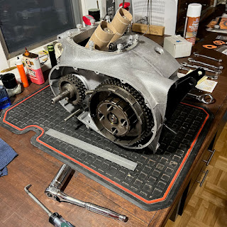
 The clutch was a bit knackered but still probably functional as it was found. The primary chain was stretched out as the "Wardmaster socket" under the adjusting pad would indicate. This has been a common occurrence found on old bikes when I tear them apart, although two out of three had lug nuts under them. Chains must have been expensive, hard to find. or not considered worth replacing "back in the day".

Tired but still serving its purpose.

"Wardmaster socket" taking up the slack. 

New bearings & rubbers ready to bring together.

My secret weapon for putting in cush rubbers, 
It makes a seemingly impossible job very possible. 

New bearings, friction plates, greased and ready to go. 

Sprockets fit without the chain to check alignment. All is good....

Primary parts ready for final installation & a timing disc setup being worked out. The final assembly will be done in the frame. On to the transmission & timing side.....

Timing/'TDC setup sorted. 
This will be revisited when the wiring is finished and the electronic ignition needs to be set. 

Assembly of the primary side was pretty straightforward. The rotor and stator went on passing the dollar bill test with no adjustments needed. The stator wires were fished through the case via the zip tie I had installed earlier. I am glad I did not forget that step as it is a real time saver 

Although I have never done this before I lightly oiled the clutch plates with type F automatic transmission fluid. I have always assembled them dry and they are usually oil soaked when removed. An expert in the field recommended lightly oiling them so I will give it a try. One thing that gave me fits was installing the clutch springs. Try as I might I could not get the retainer nuts to catch. After working a short while I decided to check the new springs I purchased to the originals. To my surprise they are .50 inches longer. The Lightning Rocket is specked for these longer springs although the standard Rocket springs came out of my clutch. I ordered a set of standard springs which are .25 inches longer than the originals but could not get them in either. Back to the original springs. The situation will be addressed at a later time if necessary.  Maybe a special tool?  Longer retainer screws?

The initial kick over of the LR found the clutch slipping. Luckily the '64 BSA had an access hole in the primary cover to adjust the clutch springs. Maybe this was more of an issue with the 4 spring clutch? Three turns in of the springs and all was firmed up. This will be reexamined when the LR hits the road and torque is applied. 

Primary assembled and it's on to the timing side. 

Monday, February 12, 2024

'64 BSA Lightning Rocket - Engine Rebuild PT III - Bottom end Assembly

BSA used a ball bearing main on the drive side of their crankshaft from 62-65 with a plain bearing on the timing side. I have set the crankshaft end clearance on the later roller bearing cranks which is critical but had not assembled the ball bearing crank. The ball should hold the crank in location and there are no oil pressure concerns as on the roller bearing cranks which use a thrust washer on the timing side. The factory workshop manual shows the end clearance being set from .001 to .003 for the ball bearing crank which is the same as the roller bearing ones. The only reason I could see for this is to keep side load off of the ball bearing. If the factory says do it, do it I will. 

Crankshaft and cases were dry assembled with no shims to check end clearance. After measurement the necessary shims were added to get the .001-.003 spec. (shooting for .001 with .002 max) One note on crankshaft shim cups - Modern Hofmann ball bearings have a larger center than the originals. This requires the use of a shim cup & shims from a later roller bearing motor.

The rods were rebuilt with new wrist pin bushings and the big ends were machined to remove their oval shape. New shells, bolts and nuts finished off the rebuild. The crankshaft was assembled and checked for free movement once the rod bolts were torqued down. The case internals were installed making sure to get the camshaft and its breather assembly properly inserted.  Time to stick it together....

The bottom end and its parts ready to go. One pointer is to add the high gear and final drive sprocket before assembling the motor in the frame. Not really necessary but much easier in this order. Just trying to reduce the amount of swearing it takes to put one of these together......

Moving parts balanced......machining marks tell the tale. 

The crankshaft was shimmed and all parts were installed. Yamabond 4 was applied to the cases and they were bolted together. One final endplay check was performed after assembly and all was good. 

         
The bottom end ready to go into the frame. 

The crankcase was assembled with minimal components to keep the assembly light. This eases installation into the frame. The top end, timing side bits and the primary will be added with the engine in the frame. I took this approach on my Interceptor build with good results. I did not take this approach with my Hornet and struggled greatly with the weight of the unit. Lesson learned and on we go.......  

Frame prepped and anxiously awaiting the power egg....

Protection for the frame's new paint was added, all mounting bolts were ready to go in, and it was ready to receive the lump. The rear engine mount plates were loosely attached to aid installation. Working from the drive side the motor was installed with its front mount above the attachment point and the rear mount plates below theirs. One person was on each side of the bike to work the motor in place. The protection on the frame proved to be very necessary. 

Once the motor was in and all bolts were in the frame the lower mounts were checked for shimming. It is important to add washers to take up space between the motor and frame and not to pull the frame to the motor. (These shims are shown in the spares manual.) Bad vibrations will occur if this is not done properly. I also scrubbed the paint off of one lower mount so the engine will ground to the frame. Probably not necessary buy my electrical engineer friend says it is wise to do so I do.....

The motor is in and being built up. Adding the power egg without its heavy components worked well for two old dudes and will be my go to method. It was installed with the front mount high working it down and the rear mount a bit low working it up. This is opposite of what I have read but it worked very well.